After learning of multisim and ultibroad, I almost understand their function and usage in the field of engineering. We learning the way to creat, design, and analysis our circuit on multisim and transfer it to ultibroad. The ultibroad allows us to modify and visualize the real circuit on circuit plate by provide 3D view.
And it is almost the time to test our understanding on both of this software.
On tuesday, we having our test on software multisim and ultibroad, everything must be precise in order to avoid any mistake and error while making the real circuit.
Everything is going smooth on the morning of that day, our director explain the test and what he wants us to do on the particular circuit.
I success to creat 2 circuit on multisim, success to let the buzzer sound and make the LED light up. I transfer the circuit to ultibroad. Before this, I replace all the virtual component to real component and confirm the number of component as well as the wire.
When doing the ultibroad, we have to check back the circuit that we creat in multisim to make the connection bocome smoothy. This is the most difficult part because many error will occur like overlaping the wire. I tried many time to make the circuit correct, and my design was so satisfy. But, something unfortunaly happen, the computer jam and everthing is gone expecially my afford. I tried to search help from my director, but he also undefine the problem that occurred just now. I so dissappointed but i decided to redo even no much time is left.
I tried to make the circuit become simple and at least it can function well. After creat, I click the button on screen and transfer it to 3D view, but the bad thing happen again. I knew that I do not have time to redo again, so I give up. Because of this decision, I loss half of my mark in this lab test. I almost want to cry, how a unlucky day!!!
Nevermind, I need to be more hardwork on the next time, everything will be fine~haiz~
Thursday, 24 November 2011

Thursday, 17 November 2011
Learning Multisim and Ultibroad is Crucial as An Engineer
This week lecture is teaching about the usage of multisim and ultibroad, two of this software are smart enough to modify the real electrical circuit that including the electronic component and the flowing of current and voltage. The lecturer showed that the different version of the software and their improvement over the year.
Multisim is a window friendly software and is really convenient for design and analyse the circuit. It allows the user to insert different type of electronic component including basic component, input source and even some virtual sources. The user can alter and set up the value of the electronic devices, so that make the circuit function well. It allows the user to creat either series or parallel circuit, analyse and test the efficiency of the circuit by testing the voltage, current, resistance of the component.
Multisim allow the engineers to design their own electric circuit and transform it to another software that is ultibroad. Ultibroad will show the arrangement of the devices on the real electrical panel. It also show the 3 Dimension of the panel and allows the user understands the circuit completely. But, the ultibroad restrict the using of virtual component, this make the circuit fail to transfer correctly and causing the serious error.
As an electronic system engineer, it is really important for us to manage the usage of Multisim and ultibroad, because it will completely related to our real project later. It as the starter of creating a panel...


Multisim is a window friendly software and is really convenient for design and analyse the circuit. It allows the user to insert different type of electronic component including basic component, input source and even some virtual sources. The user can alter and set up the value of the electronic devices, so that make the circuit function well. It allows the user to creat either series or parallel circuit, analyse and test the efficiency of the circuit by testing the voltage, current, resistance of the component.
Multisim allow the engineers to design their own electric circuit and transform it to another software that is ultibroad. Ultibroad will show the arrangement of the devices on the real electrical panel. It also show the 3 Dimension of the panel and allows the user understands the circuit completely. But, the ultibroad restrict the using of virtual component, this make the circuit fail to transfer correctly and causing the serious error.
As an electronic system engineer, it is really important for us to manage the usage of Multisim and ultibroad, because it will completely related to our real project later. It as the starter of creating a panel...
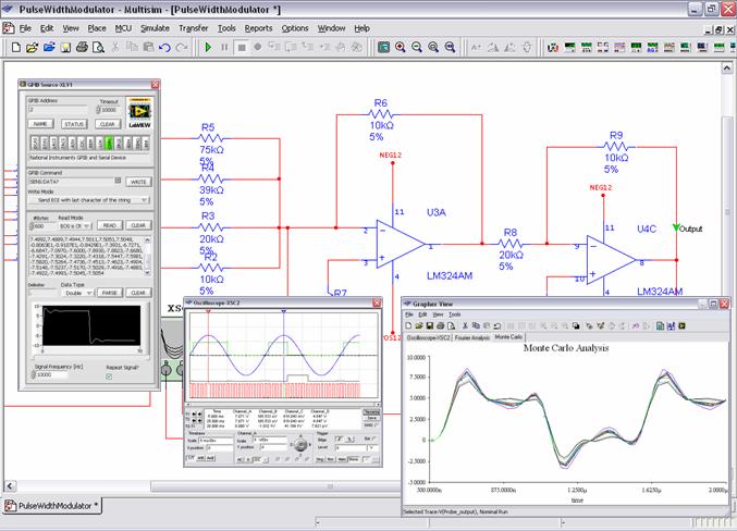
This is the example of multisim...

This is the example of ultibroad...
Monday, 14 November 2011
Important Device Introduction
This lecture was giving briefing about some important device including IC, organic LED and soon. The devices were using widely in all electrical applicances nowaday to perform crucial function. The devices perform specific task and they made the applicances become more sustainable and perform perfectly. All the devices work together in the electrical circuit simultanously and make the applicance more fulfill the demand of the human nowadays...

The picture showed some component in the electrical circuit, all of them are important electronic device!

The picture showed some component in the electrical circuit, all of them are important electronic device!
Saturday, 29 October 2011
Challenging Week!!!
This week really full with challenging stuff, one practical test and one oral presentation.
I was really surprise that i still remember the method to take measurement of electronic device by using multimeter and component analyser, this means I really concentrated on class...haha..
With the mistake I realised after the test, I found my weekness on this subject and I should find out some solution to solve it.
That is read more and do more!


In the oral presentation, I felt that everyone was great and I really learn more about the other electronic gadget. It is about the knowledge on the way it function and their application.
In my group's presentation, I felt very nervous but finally I did it. I knew it wasn't my best perform and wish that I will become better on the next one.
I was really surprise that i still remember the method to take measurement of electronic device by using multimeter and component analyser, this means I really concentrated on class...haha..
With the mistake I realised after the test, I found my weekness on this subject and I should find out some solution to solve it.
That is read more and do more!

Farhan, Uzair, and Wan explained about global positioning system.

Chin Yap, Chi Wah, and Zhi Jie explained about optical fibre.
In my group's presentation, I felt very nervous but finally I did it. I knew it wasn't my best perform and wish that I will become better on the next one.
Tuesday, 25 October 2011
Monday, 24 October 2011
Wednesday, 19 October 2011
I light up the LED...
Diode is a special device that having many functions.
It act as a valve that only allow 1 flow of current, as a bulb give out the light, as a filter in circuit also.
Diode consumed power and causing the voltage drop.
 See how I measured the LED ( light emitting diode ) by using multimeter, as the voltage flow through the LED, it light up. It proven that I connected it with the correct way because diode is polarity.
Upon the diode has polarity, it is necessary that we defined the anode and cathode of diode.
Otherwise the device will burn out.
This week we also learn the transistor device.
When lecturer asking what is the function of transistor, no one of us can answer the question.
Actually transistor uses for control voltage, as a switch and amplifier. Transistor divides to NPN and PNP type. The lecturer explained about the usage and the method of analysing the transistor of circuit.
By using multimeter, we can easily detect the type of transistor and the pin of transistor.
As we find out the the base pin, we can easily find out the collector and emittor.
Another method is by using component analyser, this is the faster and easier method to analysed pin and voltage of transistor.
It act as a valve that only allow 1 flow of current, as a bulb give out the light, as a filter in circuit also.
Diode consumed power and causing the voltage drop.

Upon the diode has polarity, it is necessary that we defined the anode and cathode of diode.
Otherwise the device will burn out.
This week we also learn the transistor device.
When lecturer asking what is the function of transistor, no one of us can answer the question.
Actually transistor uses for control voltage, as a switch and amplifier. Transistor divides to NPN and PNP type. The lecturer explained about the usage and the method of analysing the transistor of circuit.
By using multimeter, we can easily detect the type of transistor and the pin of transistor.
As we find out the the base pin, we can easily find out the collector and emittor.
Another method is by using component analyser, this is the faster and easier method to analysed pin and voltage of transistor.
Subscribe to:
Posts (Atom)